Software system dPIPE
")
dPIPE 5.27
There was discovered an error in the dPIPE 5.27, Build from November 15, that led to an inaccurate calculation of stresses in the “standard” tee elements analyzed according to the Russian PNAE or RD (boiler) Codes. The error may appear if the values of tolerances (parameters CR & CB) for these elements were not defined explicitly. The new setup with correction (from November 18) is available on the site.
dPIPE 5.27
1. The printout of the allowable loads for supports from the "OTT_0157-2013" catalogue has been corrected
2. The error of reading data from the CUSTOM table (database file “sup_lds.mdb” with the permissible loads on supports) has been fixed
3. The input of data for the modeling of Cross Tee has been fixed
4. Manipulation with comments rows is fixed for the Layout spreadsheet
5. The check of the minimum wall thickness in comparison with the wall thickness of the reference section has been corrected for the BEND element (the strict inequality has been changed for a non-strict one: SMIN ≤ S ref. section)
6. The recording of the file with TEE element’s stress time histories (TH_OUT parameter): has been fixed: originally, if there was no output of other time dependencies, the file was not written or an error was issued
7. The output of the valve’s accelerations required by the OTT check has been corrected: in the case when several dynamic design cases exist, the accelerations of the valve were displayed for the last DLC only. Now the maximum values among all DLCs defined in the analysis are printed out
8. The "optimization" operation for merging of different branches of the computational model has been improved: now it’s available for selected piping segments
9. The assessment of the accumulated fatigue damage using the FATG command is blocked for the analysis of high-temperature piping according to the PNAE Code (CODE = ‘PNAE_T’). The exception has been left for calculations with the “Simplified calculation” option (FATG_SAF = ‘YES’)
10. The option "Delete unused data" available under the command "Tools/Optimize model" has been improved
11. Assessment of the calculated vs permissible loads for spring hangers was corrected for the TEST and TEST_B analyses types: if the springs are locked in these regimes there is no need to check a permissible load for springs
12. The option to choose beam’s section has been added for the "FROM" command In the LAYOUT spreadsheet
13. The check of the maximal number of records in the file "vlv_ott.dbs" (a database with OTT allowable loads for valve nozzles) has been introduced. The maximum allowed number of records has been increased to 5957.
14. The rule "RVRS" has been added for stresses from occasional loads, which defines that dynamic seismic loads are reversible. This rule applies to calculations performed according to ASME Code (edition after 2010) or EN (edition 2020).
15. The option to read the CTRL command from the "solv.dbs" file is added. In this case, the explicitly described parameters from the database replace the existing ones and add the missing parameters to the CTRL command in the *.dp5 file
16. The crash of the program has been fixed occurred when entering the weld coefficient in the "Piping Sections" table
17. The printing of warnings (“!” sign) in overloaded valves displayed in PIPE3DV by the command “Element parameters” is fixed
18. The record of the database with pipe cross-sections (file pipe.dbs) is fixed: RD norms, standard "OST 108.320.102-78": link to the reference section for the pipe stamped elbow ‘CS530x65’ changed from ‘CS490x90E’ to ‘CS570x95
19. The record for S_III stresses (RD Code, file “SOLV.DBS”) for the joint calculation of high and low-temperature piping has been corrected
20. Option for the assessment of stresses due to seismic anchor movement separated from the seismic inertial loads has been added for Codes ASMS NB/NCD, edition 2010 and later: in the POST command for stresses RES = 'EQ9_C', RES = 'EQ9_D', the rule 'SAM' is introduced
21. Printout of maximal stresses for the BEND elements according to ASME NB Equitation (12) is recovered for the table with fatigue analysis results (section “SUMMARY TABLES WITH RESULTS OF ANALYSIS”, file *.res)
22. Fixed the work of the "Advanced" tab of the "Operational modes" table (data entry for calculating stresses from the temperature gradient). Applicable for PNAE and ASME NB Codes
23. Input of comments in the table with restraints has been fixed: before it led to the abnormal termination of the program.
24. The calculation of the postulated rupture locations of high-energy piping is realized for analyses undertaken according to the 'EN' norms
25. Changes according to edition 2020 of the EN 13480 "Metallic Industrial Piping" Code are implemented in the dPIPE
26. The option for selection of the criteria document between ANSI/ANS 58.2 and SRP Section BTP 3-4, NUREG-0800 is added for the HELB analysis, see parameter DOC at POST_HELB command
27. A summary table with the location of postulated ruptures (breaks and cracks) is added in file *.sup (HELB analysis).
CVSPEC-TH:
1. The command "Mutual multiplication of spectra" has been renamed to "Modify spectrum" with the ability to multiply / divide the selected spectrum by the reference curve
2. The option "apply only to selected records" is implemented for the command "Replace in names"
3. The procedure for calculating the response spectra has been modified: the refinements affected the high-frequency range and high damping values
4. The functionality for calculation of response spectra from accelerograms when setting frequency-dependent damping in accordance with RG 1.61 has been added
PIPE3DV:
1. The display of the rotated local axes of the beams is fixed.
2. The display of the node labels, miters bends and rigid struts transferred from the dPIPE model to the DXF file is fixed
3. The coloring of support's seismic groups for elements adjacent to piping supports is corrected
4. The algorithm for drawing the local coordinate system of piping segment located at an angle to the horizontal plane is fixed
dPIPE 5.27
1. The error occurred during dynamic analyses when the calculated spring load exceeded the maximum value has been fixed.
2. Calculation of stresses EQ11, SGM4, SGM5, where the input parameter has referred on stresses calculated with the "MAX" rule (EQ11, SGM4, SGM5) has been fixed
3. All tables with input data are redesigned. The column with comments is added to every table
4. Fixed the error that occurred when assessing the valve’s nozzle loads according to NP-068 in the frame of dynamic analysis with an option “Small Bore Pipes”
5. An unnecessary run of the modal analysis has been fixed (this situation happened when the modal LC was set before other static LCs)
6. Key's shortcut CTRL-F4 is set for the close of the current window
7. The procedure of stresses S2 calculation in the frame of dynamic analysis with small bore pipes option is corrected
8. The functionality for the input of the element 3-way Valve is restored
9. The output of “PARAMETERS FOR DYNAMIC ANALYSIS” has been specified (File *.out, Listing of Input Data). Now these parameters correspond to the data set in the first dynamic load case (DLC)
10. The output of stress intensification factors for models containing both 1st and 2nd safety class pipes has been fixed.
11. Calculation of section modulus ZB & ZR for “standard” tees have been corrected for fatigue analysis in the frame of ASME NB Code
12. The output of SRK and KE values (they appear in the printout if SAF > [SAF]) has been fixed for analysis with Small Bore Pipes option
13. The warning message instead of error will appear in case if the insulation will be detected on the internal pipe (jacketed pipes)
14. Additional check if the height of the branch is defined will be done for standard tees having different from the matched pipe outside diameter and wall thickness
15. the parameters for the SIF calculations are specified in the input dialogue windows of the WELD and REDUCER elements
16. The parameters for the SIF calculations have been clarified in the input dialogue windows of the WELD and REDUCER element (applicable for ASME B31.1 and EN codes)
17. The setting of FATIGUE analysis is disabled for all norms except ASME NB and PNAE (the FATG command)
18. Functionality of the calculator is inserted in the fields for the coordinates of the node (node properties, POS command)
19. Unintentional conversion of relative paths to the database to absolute has been fixed (command DBF)
20. The context menu item "Delete rows" of the "Geometry" table has been moved above, under the item "insert row". Added confirmation when deleting a row
21. The proper work for the export of piping sections from the table with the same name to the external file has been restored
22. Corrections have been made for the set of dynamic analyses (THA) with and without the seismic anchor movements
23. More strict check of the material properties dependent on lifetime is introduced (applicable for RD and EN codes)
24. A context menu for inserting/deleting rows is added to the Table “Analysis Specification”
25. A check if the declared response spectra contain data is added
26. Tables «LISEGA2010RSENR2» and «TITAN-2_R1_7» were added in the file SUP_LDS.MDB containing allowable loads for piping supports. These tables contain data from the following Manufacturer’s catalogues:
“Catalogue of the standard elements for piping supports for ISO 4200:1991 pipes”, Revision 1.7, JSC “TITAN-2 holding”;
“Standard Supports 2010 RS EN. Addendum to LISEGA catalogue “Standard Supports 2010" in reference to Russian standard pipe dimensions for nuclear application, Rev. 2” by LISEGA
The structure of the file SUP_LDS.MDB and the command SUP_LOADS have been changed to allow the following features: now it is possible to set the rated permissible load and tables with correction factors applied depending on the seismic category of the pipe and the operating temperature. A detailed description is given in Appendix XII of the User Manual (help file)
27. The following spring tables from the TITAN-2 catalog were added in the file with characteristics of the springs (SH.DBS): ‘T2’ – springs with working range 50, 100, and 200 mm and load capacity up to 100 kN; ‘T2_XL’ – springs with working range 50, 100, and 200 mm and load capacity from 53 up to 400 kN; ‘T2_RU’ – springs with working range 70 and 140 mm and load capacity up to 58.5 kN;
28. It was detected that directions of STX and STY restraints and components of supports displacements were incorrectly determined after operation “Rotation of the model around Z-axis”. This error has been fixed
29. An option for the selection of the spring of the determined type has been realized. In this case, spring id should be defined in *.dp5 file as id = ‘0/0/25’ (25 is spring type from the corresponding spring table)
30. File MAT.DBS with materials data: for steels with the designation $12X1MF and $15X1M1F* (code RD), an explicit indication of the lifetime of 100 thousand hours has been added. Before that, when using these materials, the lifetime was assumed to be 200 thousand hours by default
31. The printing of stresses in the PIPE element that models the standard tee branch from the RUN axis up to the RUN surface is suppressed if the ratio between mean radiuses of the BRANCH and RUN is less than 0.5
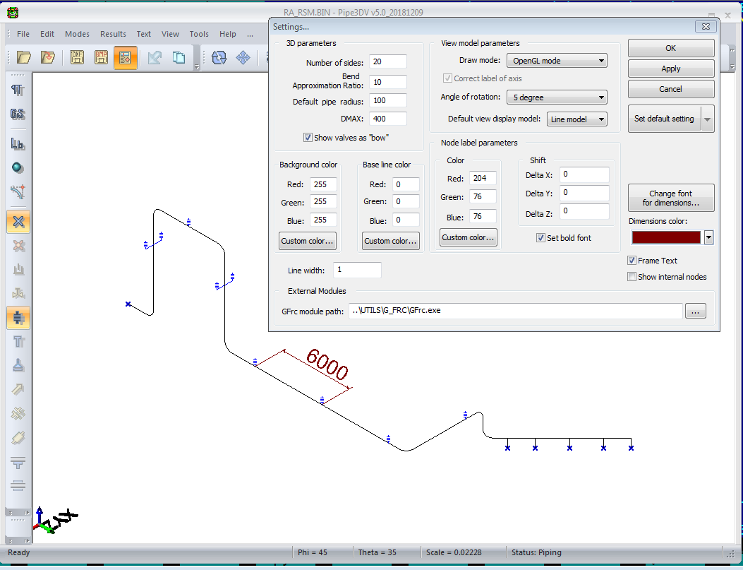
32. An optional show of the stresses in the external “transparent” pipe is realized:
![]()
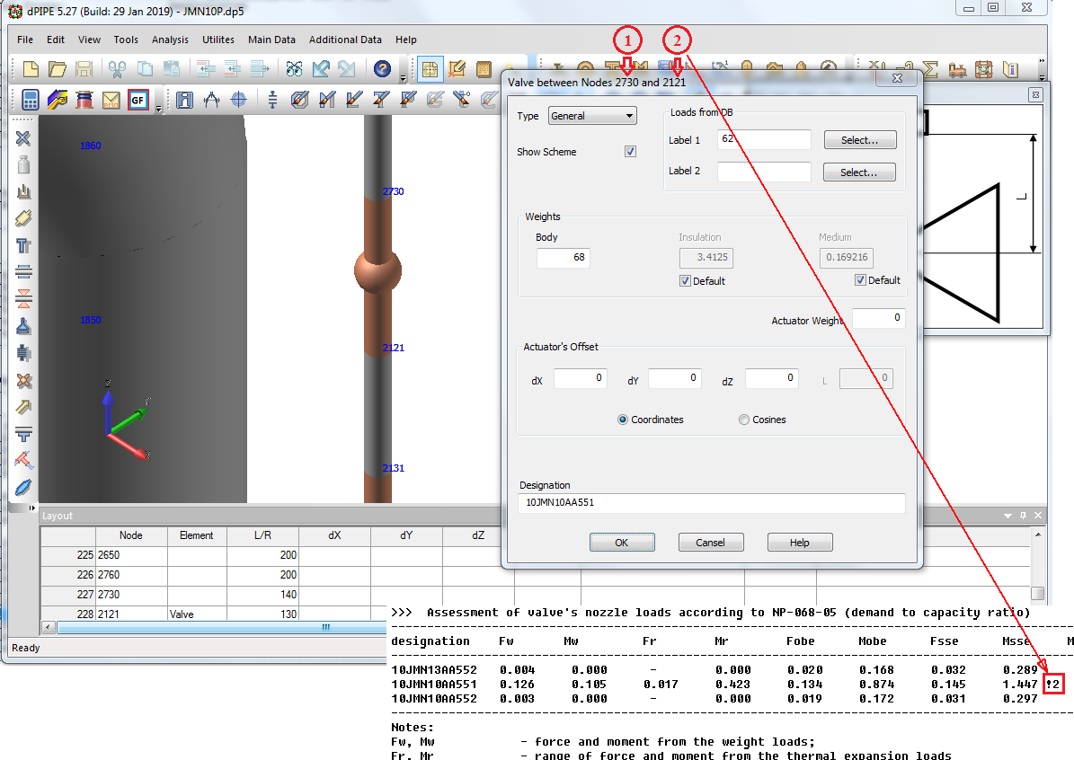
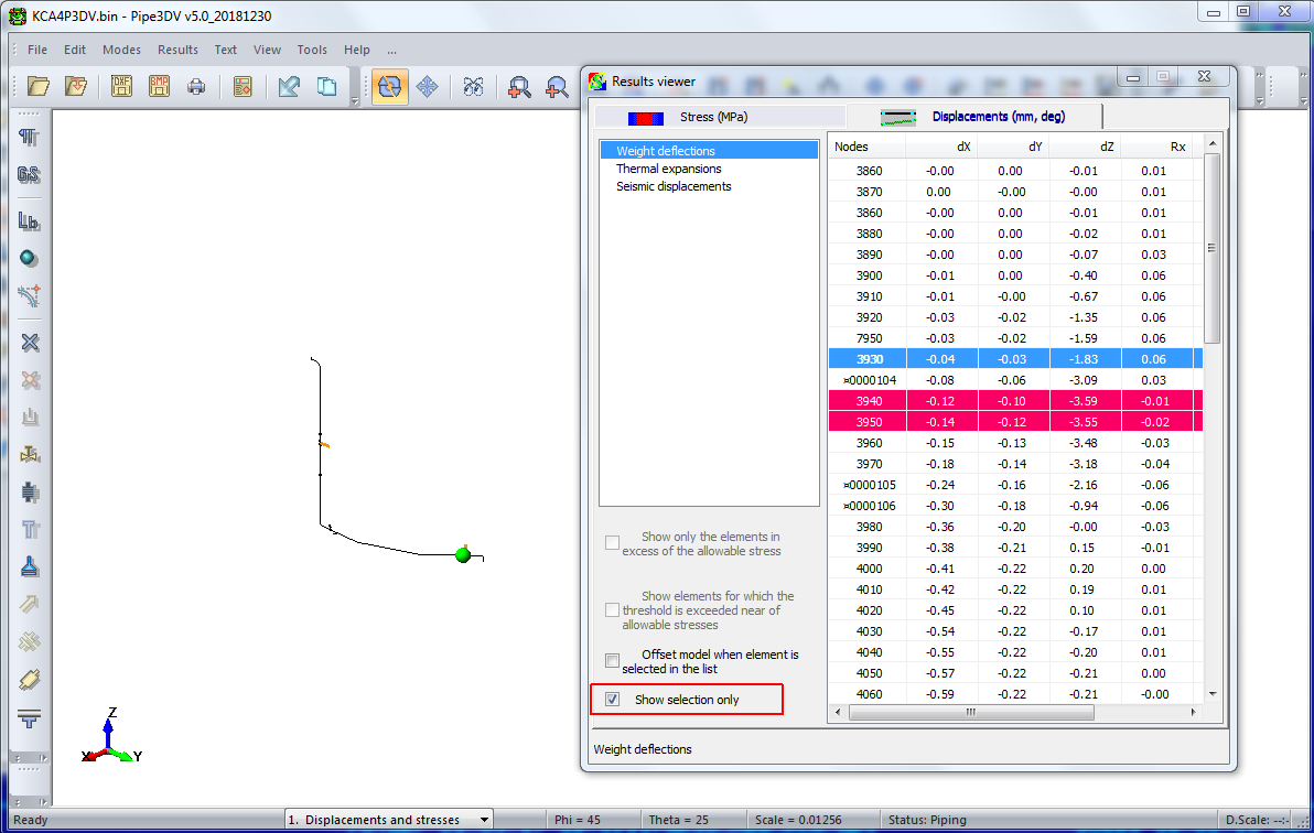
33. The valve’s nozzle loads assessment results could be seen in PIPE3DV through the "information for the element". If results are negative elements are blinking and a red exclamation sign appears in the right top corner of the window. The blinking can be switched on/off with the use of the ALT-SHFT-E shortcut.

>>>
1.4mb
34. Similarly results of the piping supports load capacity assessment could be seen in PIPE3DV through the information for the node. Supports with unacceptable results are blinking If the criteria are not satisfied, then a red exclamation sign appears in the right top corner of the window. The blinking can be switched on/off with the use of the ALT-E shortcut.
35. The export of the calculational model geometry from PIPE3DV to the DXF file has been fixed: elements "rigid struts" have been added, the display of miters and names of nodes of the model has been fixed
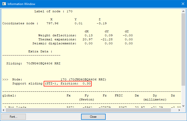
36. PIPE3DV: for guides and sliding supports, their type (STG/STG-, STZ/STZ-) and the value of the friction coefficient used in the calculation have been added to the "node information". For spring supports - the friction coefficient is shown.
CVSPEC-TH:
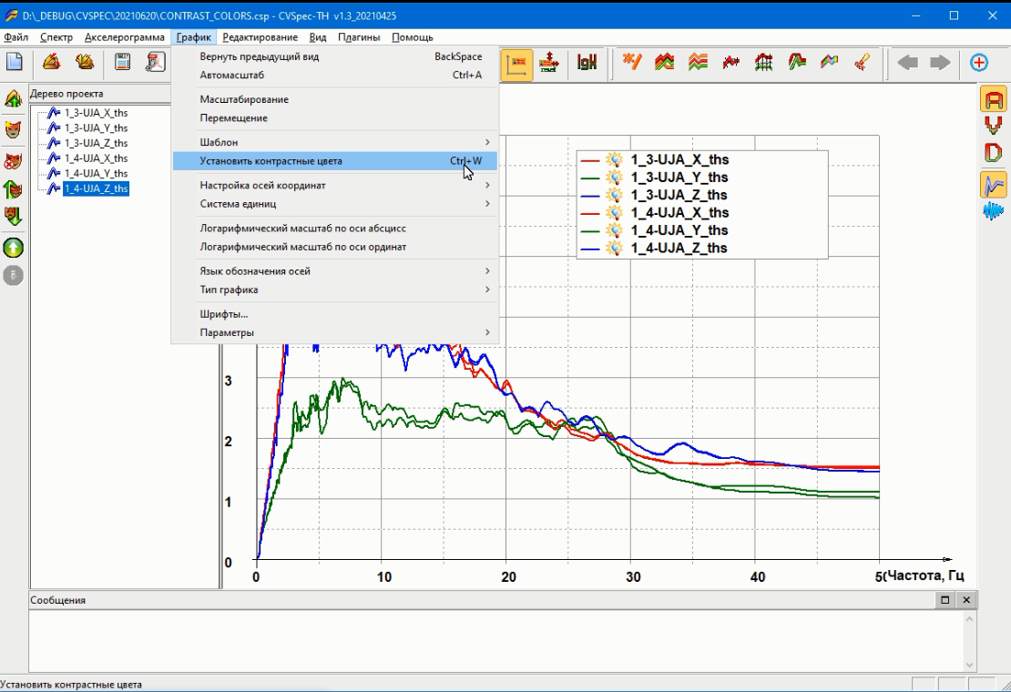
1. An operation to set contrasting colors of the shown records is added (CTRL-W).
>>>
0.5mb
2. An operation to multiply spectra by the reference line is added,

>>>
1.8mb
3. An functionality for transferring records from the "Folder" to the root of the project tree is added
>>>
1.5mb
dPIPE 5.27
1. A new command “Reset workspace” has been added to the “Tools” menu item, allowing to reset the program’s interface to the default settings (windows layout, keys shortcuts, etc.)
2. The command for search in the text and in the graphic window has been modified: the option for search with the use of wild cards has been implemented; the functionality of the command has been expanded and its interface simplified. The search is performed over the entire text of the * .dp5 file with automatic positioning of the found fragment to the window focus.
3. Processing of the parameter ANGLE of the REDUCER command representing a tapered part of the element has been fixed. Changes are relevant to ASME and EN Norms
4. Processing of the MITER element has been changed: a check of the ratio between the radius, the number of cuts, and the full angle of the element have been added. Also converting data from old formats is fixed
5. The size and position of the fields of the "valve with offset" dialog have been changed: on some laptops the dialog did not fit the entire screen and the buttons were inaccessible
6. The check of the node name length of the field "support under the body" in the element "valve with offset" has been added
7. An optional key “NOPOS” has been added to the DPC module (compiler of input data). It allows to ignore predefined coordinates of the nodes (POS command) and identify separate branches not connected with the main line of the model. In some cases, existing of separate branches may lead to the error "non-positive definite matrix". Command syntax (run from command line): dpc.exe
8. The field for ID is added to the WELD command. ID will appear in the input/output listing and in PIPE3DV as well
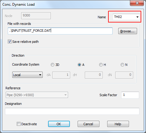
9. A summary table for the transient nodal load is added to the program interface: Additional Data/Dynamic Loads
10. An additional check is added for the "standard” tee: the setting of the component’s weight is allowed if the size of the tee is given (run length and/or branch height are defined)
11. An option for an accounting of the concentrated forces among other loads is restored for the type of Load Case “OPER_R”
12. The program's hangup is fixed occurred sometimes during working via remote access due to loss of Internet connection
13. Text search with wildcards is implemented. Searches in the text and graphics windows have been modified and corresponding icons added

>>>
3.1mb
14. Corrections of primary stress indexes B2 have been introduced for components with Do/T ratio > 50. This change is relevant for codes ASME_NC/NB 2010.
CVSPEC-TH:
1. Changes have been made to the program interface (menu items and their names have been reorganized), see the help file
2. The work with the system of units has been updated: it is assumed that all records in the project (spectra and time histories for accelerations, velocities, and displacements) are stored in mm/sec2, mm / sec, and mm, respectively. The same units are used to export data to external files or to the clipboard. To display graphs in other units, the program provides a corresponding interface (see menu item “Plot tools/Units System”).
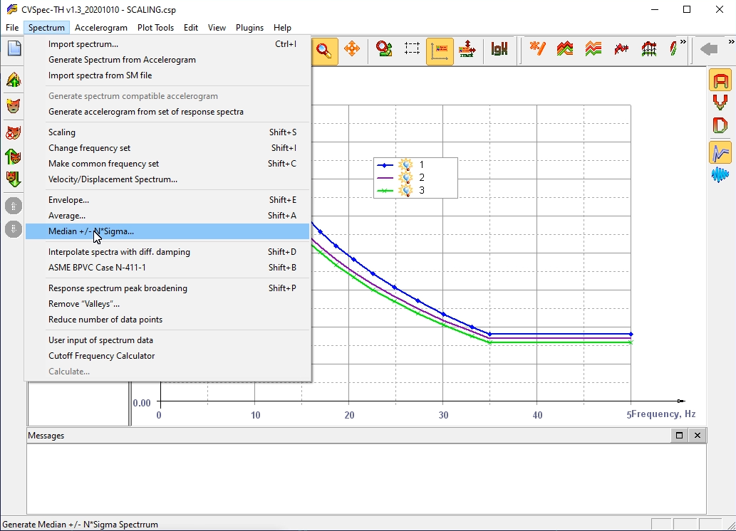
3. Developing of the median spectra has been updated. The number of standard deviations may be defined by the user (+/- N*SIGMA)
>>>
0.8mb
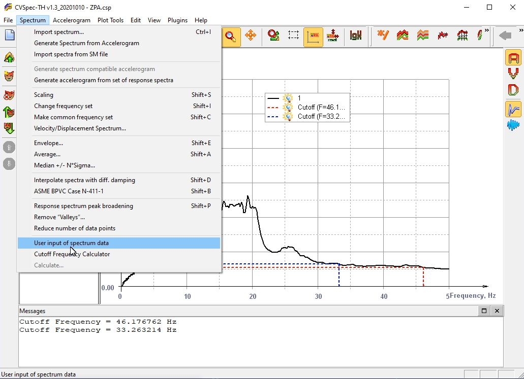
4. An option for calculation of cut-of-frequency for the specific spectrum is added
>>>
1.5mb
5. A procedure for expanding the peaks of the response spectra by a given value to the right and left of the peak is added (this option may be useful in the frame of structural analysis with soil properties variation).

>>>
1.7mb
6. Automatic saving of * .SM files created during dPIPE session is canceled
7. Procedure for grid lines is improved
8. Buttons for creating and navigating between project pages are added to the toolbar
9. Axes scaling algorithm is improved
10. Navigation along the project tree is improved (the cursor position is remembered when switching between pages)

>>>
1.2mb
G-FRC:
1. The functionality for editing a line's style by double-clicking on a chart line or from the context menu is added
1. Fixing of the small bugs in the module for transferring data from dPIPE to LICAD RS
2. The orientation of the one-directional supports (restraints) resulting after rotation of the model around axis Z is fixed
3. Processing of the relative links in *.dp5 file during project archiving is fixed (command file-make archive)
4. Fixing of the small bugs in the module for transferring data from dPIPE to LICAD RS
5. Postprocessor bug is fixed caused the failure of the problem when in the frame of one-run several different dynamic methods were utilized (RSM & THA).
6. Fixed a bug led to the program's failure if there were specified several dynamic analyses using different sets of accelerograms.
7. The bug in the procedure that involves seismic anchor movement in case of several sets of seismic inputs is fixed
8. Fixed a bug led to the program's crash occurred when calculating SGM4 stresses (CODE = ‘EN’) for load combination included a range of seismic anchor movements
9. DDE has started to show strings-comments from the dp5 file and keeps them after the model has been changed. Comments for “extra data” (any text following after semicolon) are stored as well. The corresponding interface has been added to the program interface
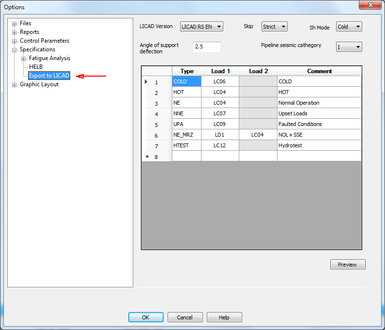
10. The command DP2LCD (export of the supports loads to LICAD software) may be exported from solv.dbs file along with specifications for “standard” analysis and postprocessor.
11. The “Optimize” operation can now be applied to the selected part of the model (see the "Change" mouse context menu available after selection).
12. An additional parameter “ref_node” is added to the extra data syntax. It’s available for those extra data that has direction and located in the node where more than two elements are connected
13. The interface for the element "miter elbow" is changed (see Help file)
14. The order of input arguments in the command POST is restricted when rule “SEISM” or “S_SRSS” is used”: for FRCS, SUPP, DISP types of results if the first argument is LS, then rest of arguments should be LS as well.
15. The content of the “Control parameters/Dynamic” tab has been modified: the parameters existing in the Analysis Specification (the “Dynamic calculations” tab) have been deleted.
16. The commands SUP_LOADS and DP2LCD can be read from solv.dbs file (specifications for the “standard” sets of analyses)
17. Calculation of Seismic Anchor Movements (SAM) has been fixed for the case when several Dynamic Load Cases were applied for the model
18. The parameter “Number of Flanges” is added for bends and miters (applicable for ASME/EN codes)
19. The procedure for fatigue evaluation considering seismic loads is fixed
20. An allowable range for the command GRAD parameters (discontinuity stresses due to temperature gradient and stratification) has been changed: the values can be either positive or negative. Similar changes were made to the STR_DISC command
21. “Liftoff” warning for supports under combination NOC + SSE (OBE) using the SEISM rule has been fixed.
22. Correction of the dampers seismic displacements by the accounting of the global Seismic Anchor Movements (SAM). This change concerns calculations when Time History Analysis was utilized and SAM was introduced through the corresponding groups of spectra.
PIPE3DV:
1. Changing the model coloring algorithm by category (colors have become more "contrasting")
2. Custom setting for the font used in the form “Element/Node Info” is added

3. Number of cuts at miters corresponds to the used number in the input data
CVSPEC-TH:
1. An algorithm of the spectra’s peaks smoothing and broadening has been improved
1. Processing of the links containing relative paths (SPEC, ACCE, DBF, DFRC commands) is added. The option is applicable when * .dp5 file is saving to another folder.
2. Processing for files with time history records (TH_OUT command) is added for the case of several time history analyses in the frame of one calculation.
3. Input and processing of the dynamic forces set are fixed. Applicable for the time history analysis.
4. Specific material may be assigned for the VALV element
5. The procedure for the location of postulated ruptures of High Energy Lines within ASME Class 1 piping HELB analysis is modified
6. The RULE = ‘RANGE’ is added for evaluation of stresses calculated by equations (12) and (13) for ASME NB-3600 Class 1 piping analysis
7. The limitation for the names of fatigue curves used for Austenitic Stainless Steels for ASME NB-3600 Class 1 piping analysis is exempted
8. Processing of the parameter HELB_STR (prefix used in the name of piping classified as High Energy line) is fixed
9. Calculation of Sm value for Equation 12 (ASME NB-3600, code year 2010) is changed: now Sm is the an average of the tabulated Sm values for the highest and the lowest temperatures of the metal during the transient
10. The interface between the results of dPIPE calculations and the LICAD program is implemented for the LISEGA supports. See details in the help file.
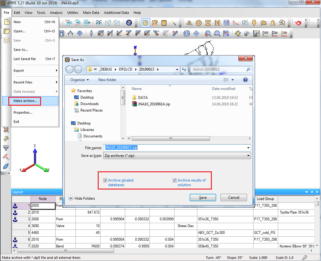
11. The option for archiving the source data files and calculation results is added. This functionality is useful for archiving projects and data exchange. This feature requires .Net Framework version 4.5 or later.
12. In the "External programs" dialog, the processing of the "Arguments" line is added with the "Request Filename" option enabled.

13. The output of Fv value (demand to capacity ratio) in the table “Assessment of valve's nozzle loads according to NP-068-05” has corrected. The bug appeared in version 5.27.
14. Executable modules are digitally signed by the Vendor.
CVSPEC-TH:
1. The check of the presence of zeros in the response spectra record is added. The program reports warning when such records are found. Simultaneously the operation for deleting zeros was added (menu item Edit, Adjust Spectra with Zeros)
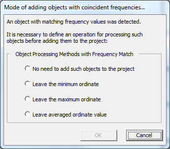
2. The spectra records are checked for the repetitive frequencies. If such frequencies are detected correction with several options is proposed.
3. Settings for the legend’s and axes fonts are added (Menu File/Settings)

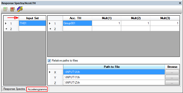
4. The functionality for the synthesis of accelerograms from the set of spectra with different damping is added.
1. A bug in the module for the printout of the input data is fixed: the program crashed if in a set for dynamic calculations a comment was specified.
2. DCASE command: an option for use of the damping parameter and seismic motion duration is added. Applicable for some types of modal combinations: CQC/DSC in the frame of Response Spectrum Method.
3. Fixed a bug in the postprocessor module, resulting in the crash of the program, when the dynamic analysis run after spring design not satisfying criteria for the spring load variation
4. Incorrect work of postprocessor module has fixed. The error occurred when LOAD CASE with TYPE = ‘MODAL’ was set in the last place. The bug has appeared in the Release 5.27 of February 12, 2019
5. Fixed a bug in the postprocessor module, resulting in the crash of the program when time history analysis has been used for small bore pipes.
6. PIPE3DV: Appearance/disappearance of piping supports in the model is fixed when the model is reloaded within the same session
1. Fixed incorrect work of the program with models containing CS elements (cold spring)
2. Processing of the stresses of categories S1 / S2 (PNAE norms) with reference to the dynamic loads set is fixed
3. Navigation and editing of the comment fields in the "Analysis specification" tab is fixed
4. The proper work of the program in demo mode has been restored. The program had been failing if the dongle was not found
5. The processing of the element “Valve with offset, VO” is fixed: the bug has appeared in the Release 5.27 of February 12, 2019
6. The processing of the dynamic force in the frame of dynamic time history analysis has fixed
7. The problem with number of modal analyses more than two is fixed
Analysis options:
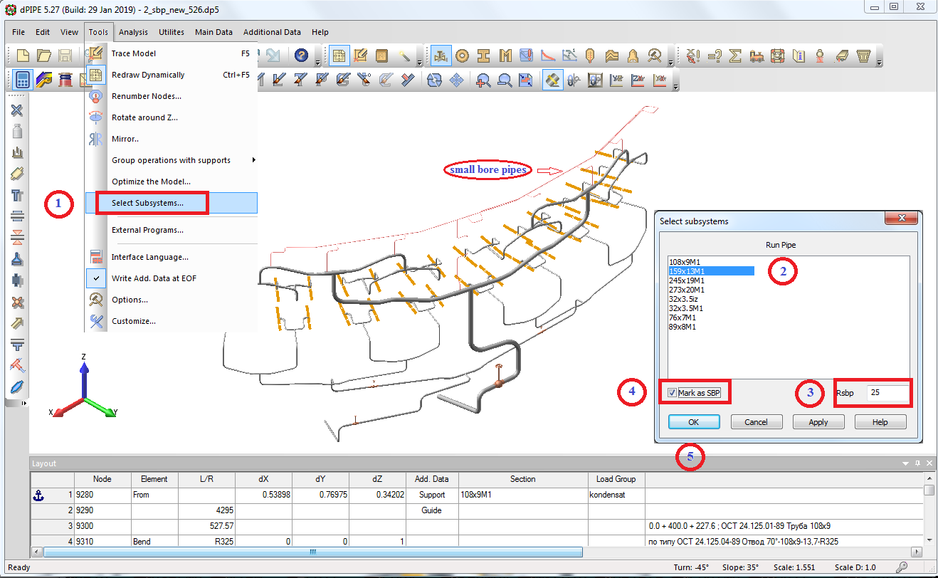
1. Engineering approach for seismic analysis of small bore pipes is implemented (see Appendix XV in the help file):
2. Option for the solution of several dynamic load cases in the frame of one model is added:
The commands SPEC, ACCE and DFORC were modified in this regard:
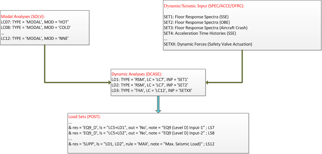
The commands SPEC, ACCE and DFORC were modified in this regard:

The tab with “Dynamic Analyses” has been added to the SOLV & POST specification window.
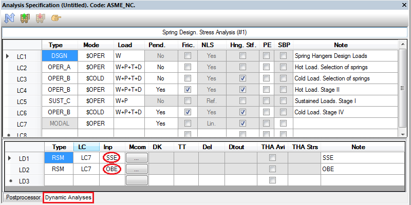
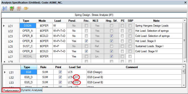
Reference on the dynamic load cases should be made in the postprocessor commands:
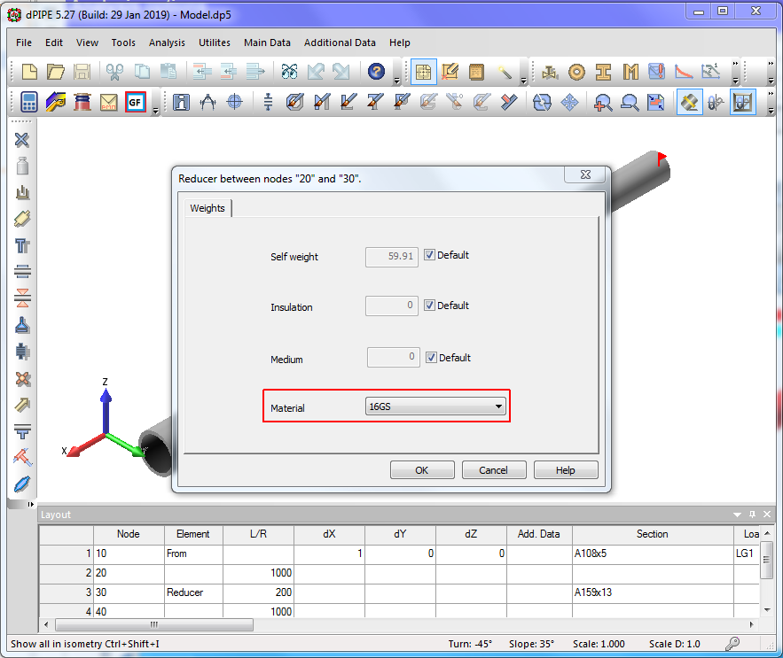
3. Element REDUCER got the reference on the specific material
4. Added option for assessment of loads acted on rigid struts with use of support's database (sup_lds.mdb file)
5. The rule for selection of Operational Mode compatible with the calculation of seismic stresses is changed: now it is taken from the reference of the first member in the load case combination used as a reference for seismic stresses. The previous approach used operational mode defined for the modal load case. This change may be useful for load combination Abnormal Conditions + Seismic Load.
6. Printing of the summary table with fatigue analyses (cumulative usage factors) results has restored. This problem has appeared in the last release of the program for models without predefined names for piping segments...
7. The processing of the “standard” tees has been fixed for the seismic anchor movement analyses in the frame of dynamic time history calculations
8. Calculation of the allowable stresses used for SGM4 stress category (EN-13480 Code, 2012 ) is corrected (stresses has become higher)
9. An indication of the point where the loads on the valve’s nozzles have exceeded the allowable values according to OTT assessment is added in the printout:
10. Calculation of the allowable stresses used for SGM2 stress category (EN-13480 Code, Sub-Clause 12.3.3) has updated considering allowable stresses for the occasional loads (parameter SOL in the MAT command)
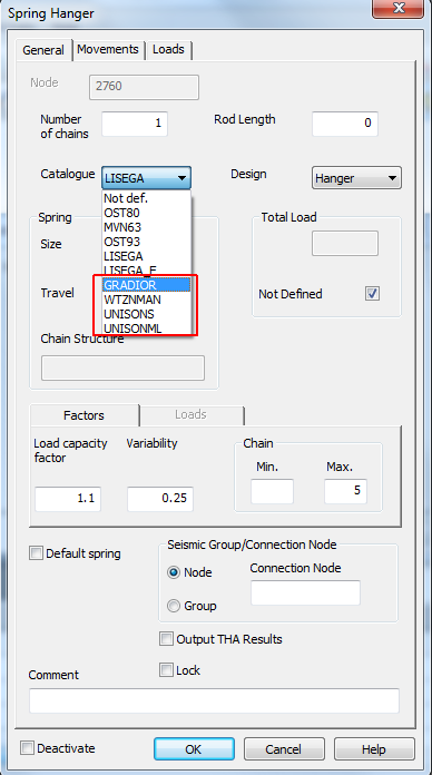
11. Spring hanger’s database (sh.dbs) with characteristics of springs is upgraded with data from the catalogs of the following vendors: WITZENMAN, UNISON and GRADOUIR
12. The flexibility and stress intensification factors are corrected for the miter bends (this change is applicable for ASME and EN Codes)
13. Processing of the old TEE command is fixed for EN code.
DDE Spreadsheet
1. Coordinate axes and Legend may be moved along the screen with the use of (SHIFT + arrows) and (CTRL-SHIFT arrows) shortcuts correspondingly (this feature is realized by analogy with PIPE3DV)

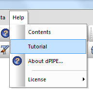
2. In the "Help" menu item added "Tutorial"
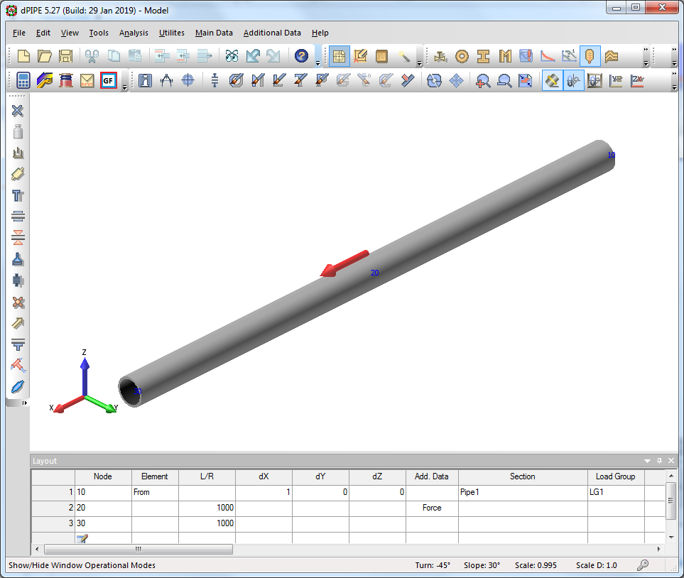
3. 3D view of the force acting along the pipe axis is improved
4. Element for Angular Valve is modified:
1) "halves" of the angular valve can be of different lengths
2) Valve’s Nozzles may have different references on the OTT database items

5. Modeling of 3Way Valve is added in the User Interface.

6. A check of the radius of the bend or miter bend is added: error message will appear if R <= D/2
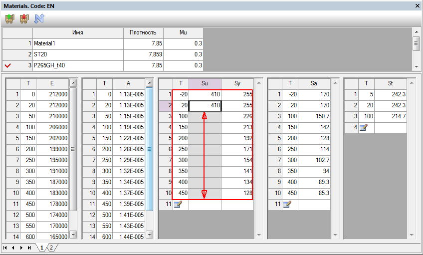
7. Editing functionality of the table with material properties is restored
8. The values for T-SR-TAU and T-SOL has been moved on a separate tab (applicable for the CODE = ‘EN’)
9. The size of arrays for the ultimate and yield stresses (SU&SY) may differ in the material table.
10. The current piping section may be assigned for FLEX element (it affects only 3D view)
11. An additional check is added for the prevention of assigning any of “External” data for the internal nodes of the valves (except for supports).
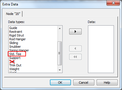
12. A conventional TEE has been removed from the DDE interface. For compatibility, the TEE command is still available in the source data file, but it is strongly recommended to use the "standard" TEE when creating calculation models:
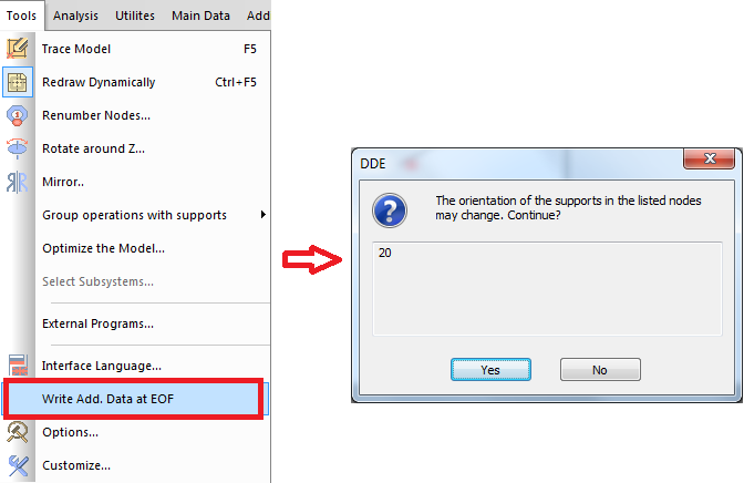
13. For the data located at the branch points of the piping, which direction is determined relative to the pipe axis (forces, guides, restraints, snubbers), the additional check has been introduced. When using the “Additional data at the end of the file” option, a corresponding warning is issued:
PIPE3DV
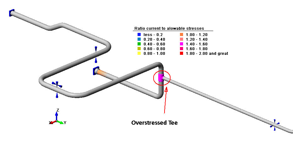
1. Graphical presentation of stresses in the area of tee joints/branch connections has been improved.
2. Option for the thickness of the line to draw the "wire" model is added.

3. Captions may use different fonts and background color (applicable in the TEXT mode)

4. Fonts used for dimensions may be modified.
5. 3D View of Dynamic Forces is improved
6. Correct export of the model in DXF file is restored
7. Results in the Table may be shown partially depending on the visible parts of the model.
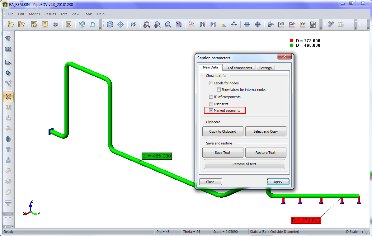
8. Option for automatic caption of the different piping categories (sections, materials, etc.) is added
dPIPE Utils
CVSpec-TH
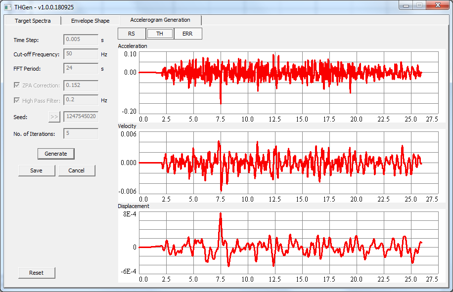
CVSpec + Sintez-M = CVSpec-TH:
New release of CVSpec software is issued. Starting from the current release, CVSpec has gained a new functionality: generation of the accelerograms from the response spectra. the program name has changed: CVSpec-TH. Please, be aware that we stop distribution of SINTEZ-M and will not conclude new contracts for its technical maintenance. All companies that have purchased the program and are under maintenance will be provided with the appropriate number of copies of the CVSpec-TH program, and our commitment to maintaining SINTEZ-M will be transferred to CVSpec-TH.
>>>
9.3mb
G-Frc
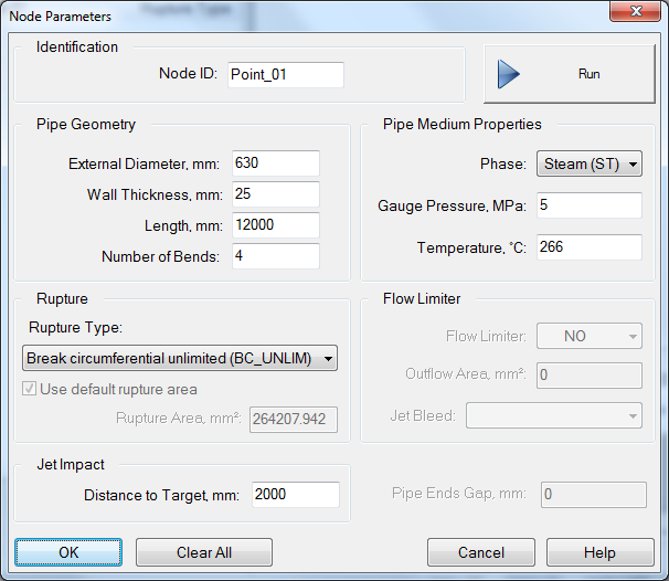
G-Frc: Calculation of the Jet Flow parameters and Fluid Flow Reaction Forces and resulting from the High Energy Pipe breaks

>>>
9.8mb
G-Frc is software for evaluation of the reaction forces exciting the high energy piping due to a release of the medium from a circumferential or longitudinal break. The program also allows assessing an impact of jet flow on the surrounding structures which are inside the zone of the jet expansion. Jet impact includes excessive pressure, temperature and wetness.
The results obtained by means of G-Frc could be used for the consequent piping dynamic analysis and also for the jet impact evaluation on the surrounding structures and estimation of their protection feasibility.
The code is based on the analytical model presented in American National Standard ANSI/ANS-58.2-1988 "Design Basis for Protection of Light Water Nuclear Power Plants Against the Effects of Postulated Pipe Rupture".
- According to ANSI/ANS-58.2-1988 G-Frc code considers for the following types of breaks:
- Circumferential break with full separation (guillotine rupture);
- Circumferential break with limited separation;
- Longitudinal break;
- Through-Wall Crack.
- For the case of circumferential break with limited separation two possible options exist:
- pipe ends limited separation at the rupture is provided by the manner of the pipe fixing at the vicinity of the rupture;
- pipe ends limited separation at the rupture is provided by the special flow limiter installation on the place of the pipe potential rupture intended for the medium flow rate reducing out of the rupture.
- The code can operate with the following mediums:
- Saturated water steam;
- Superheated water steam;
- Pressurized water with the temperature less than saturation temperature but higher than 100oC;
- Pressurized water with the temperature less than 100oC.
Two last-mentioned types differ by their ability to flash just at the rupture area.
- Jet impact on the target (civil structures, equipment, etc.) is evaluated under the following assumptions:
- the target is located normally to the jet axis;
- the target surface is significantly larger than the jet cross-section at the area of the jet impinging on the target, that is the jet impinging spot is totally disposed inside the target surface.
G-FRC can be used independently or being incorporated in dPIPE software.
Use of the program requires the protection key.
Demo version is limited only by one piping cross-section 620x25: